Appendix B Diagrams: Drawing the Runtime Skeleton
Previous chapters explained runtime structure in text. Text is necessary, but some structures become clearer as diagrams: Claude Code is an explicit state-machine system, not "a pile of prompts plus a few tools."
B.1 Diagram 1: Claude Code global control plane
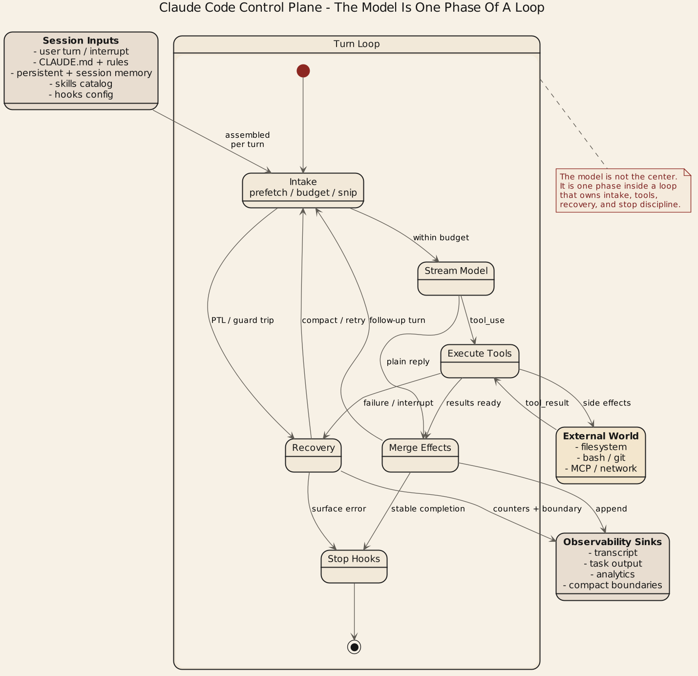
This should not be drawn as a children-book flowchart like "user -> model -> tool -> output," because that hides the actual organs. A more accurate view is five layers:
- user interaction layer
- control plane layer
- execution loop layer
- external capability layer
- persistence and observability layer
The point is not listing every module. The point is:
- model is neither topmost nor bottommost
- model is one phase inside query loop
- control and recovery planes are what hold the system together
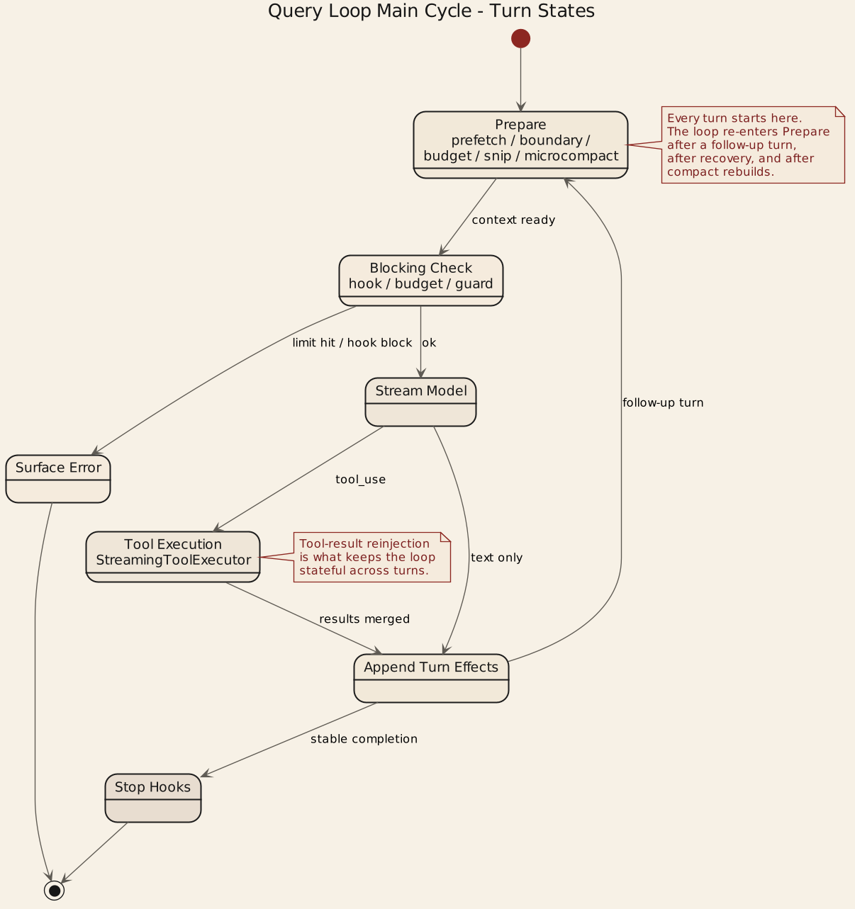
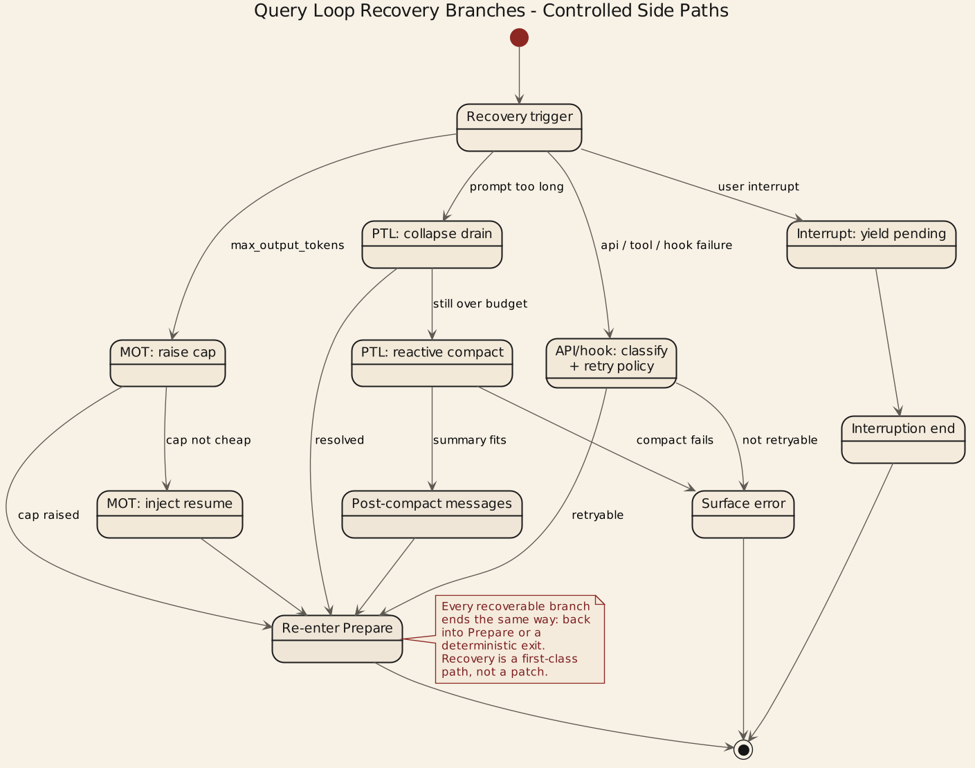
B.2 Diagram 2: Query loop main cycle and recovery branches
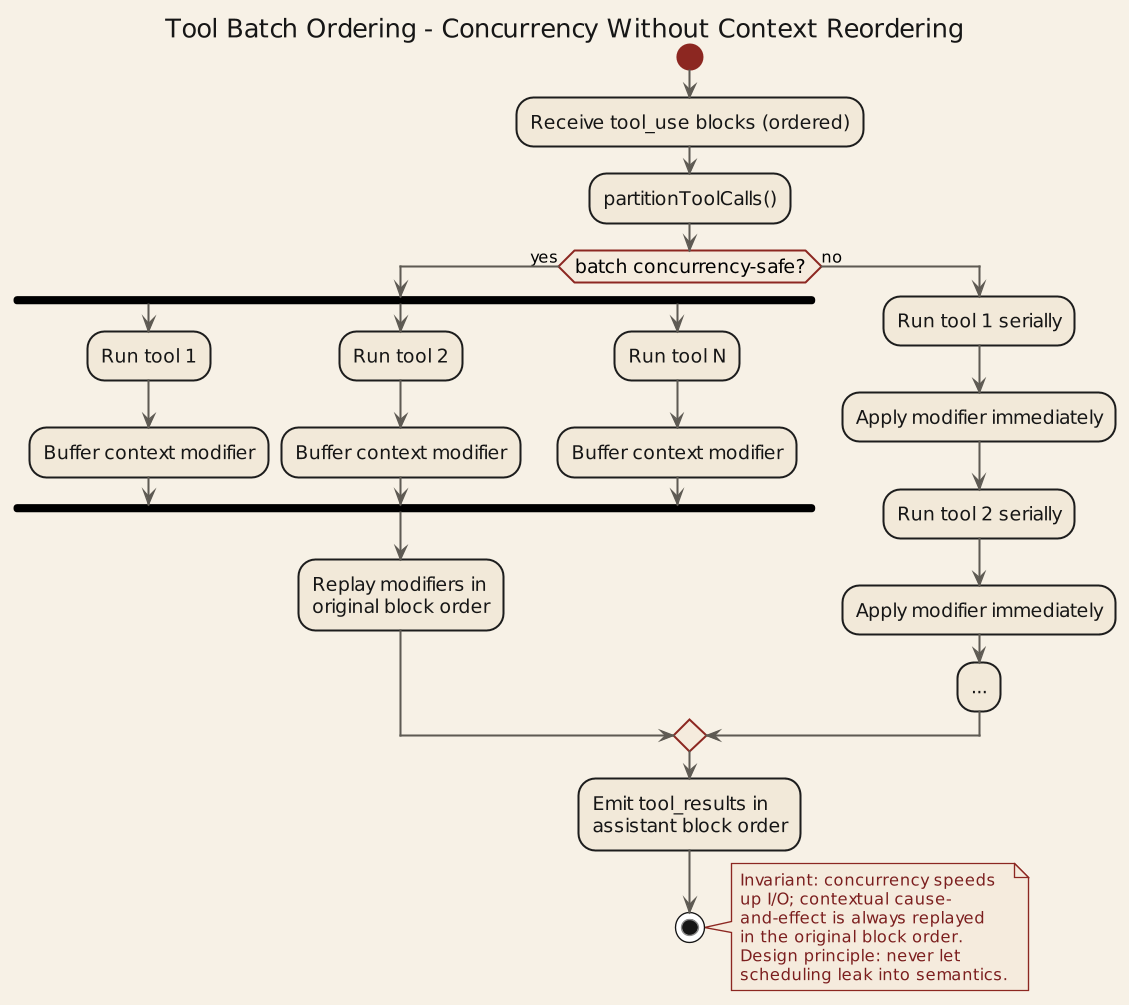
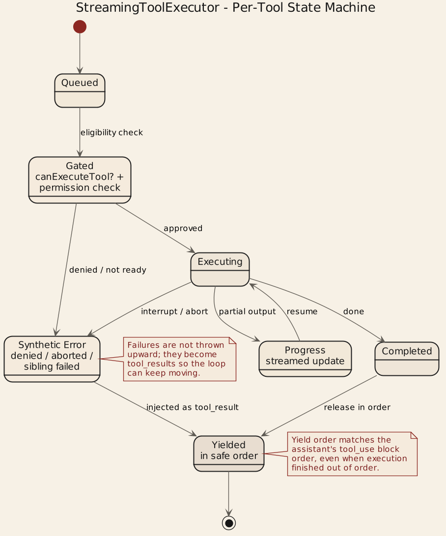
B.3 Diagram 3: Tool batch ordering and StreamingToolExecutor
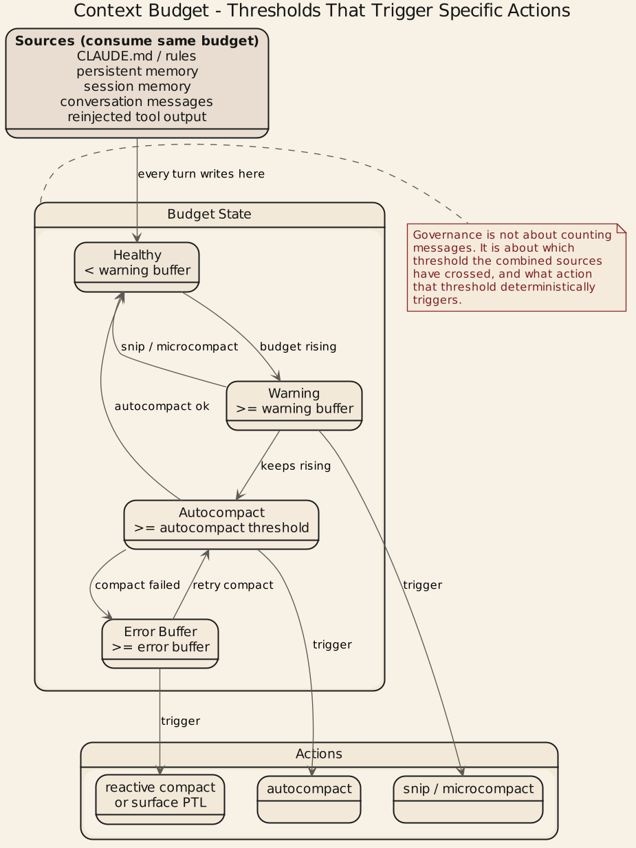
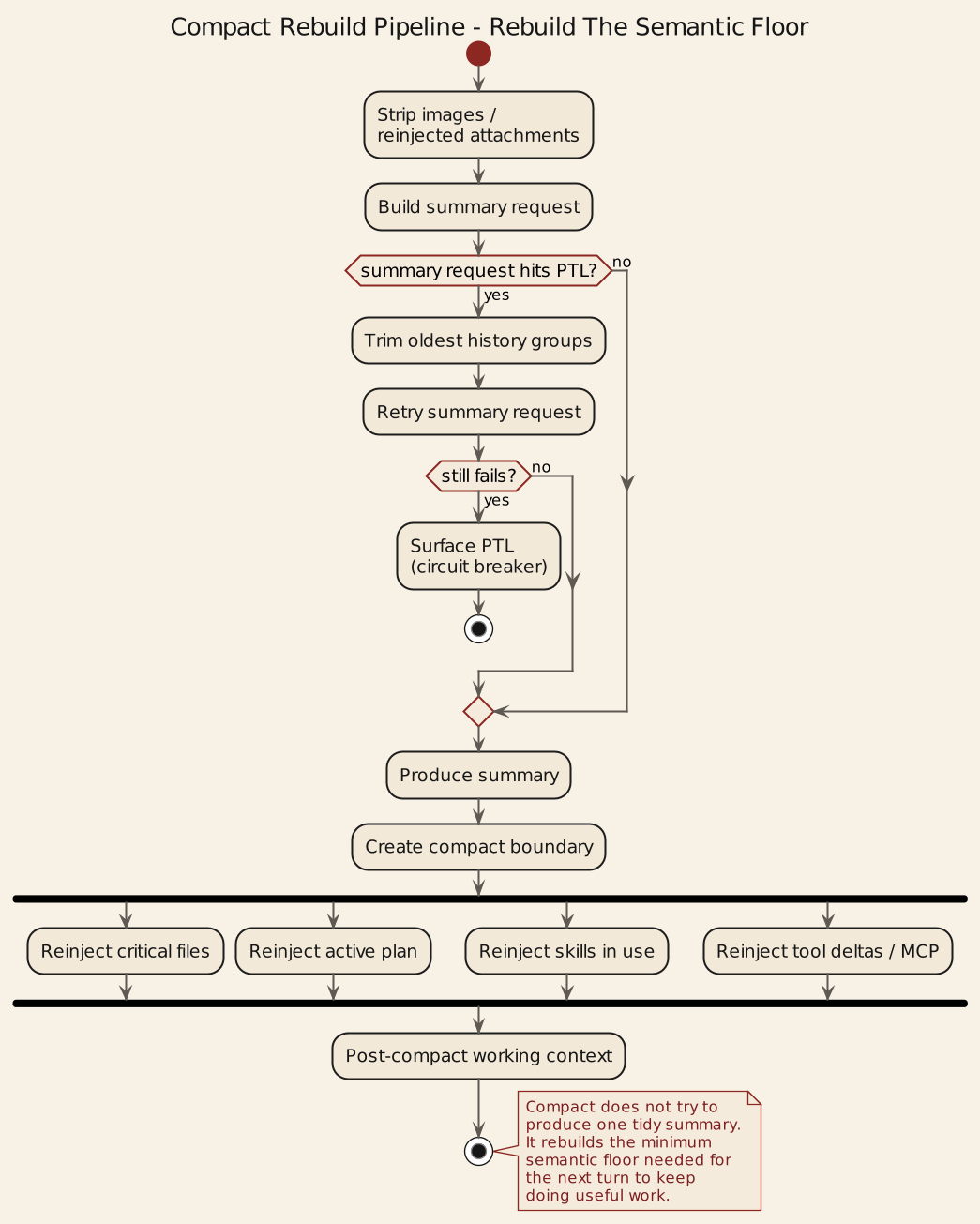
B.4 Diagram 4: Context sources and compact rebuild
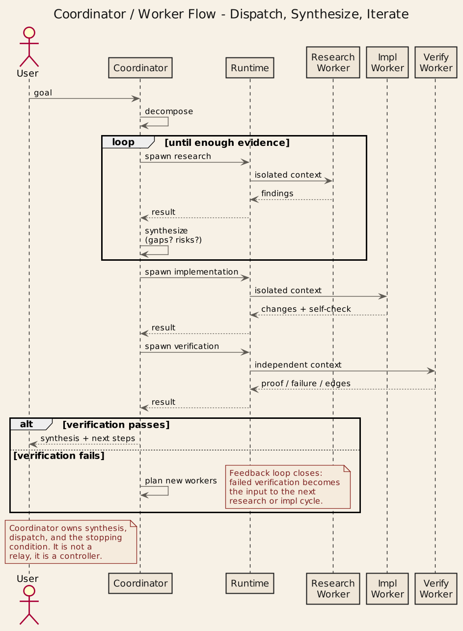
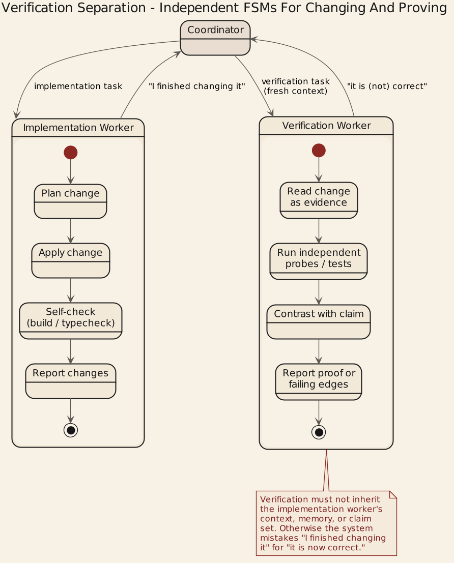
B.5 Diagram 5: Coordinator-worker flow and verification separation
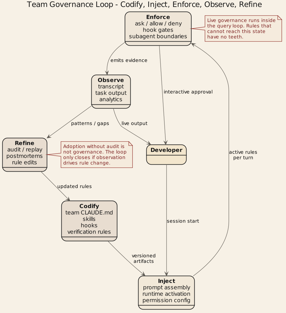
B.6 Diagram 6: Team governance map